Why force uniformity is the figure of merit
A launcher is limited by the peak force its payload can survive, but it is paid in mean force. Every unit of peak-to-mean ratio is capability thrown away. The RopeComb exists to make that ratio small with passive hardware.
Peak / mean force, launch systems compared
System Layout & Operating Principle

The target ratio profile
Impose uniform payload force F, conserve power, and the ratio the transmission must follow falls out as G*(d) = dy/dd:
- d
- the source deceleration (breaking) distance.
- y
- the payload acceleration (launch) distance.
- F
- the force on the payload, uniform by design
- M, m
- source and payload mass
- v0
- speed of the source at the entry of the breaking phase.
- g
- gravity, so 2gd is the work it keeps adding as the source falls
The denominator is the source's remaining speed and the numerator is the payload's: as the source is braked and the payload gains, the required ratio climbs, steeply at the end.
The mechanism
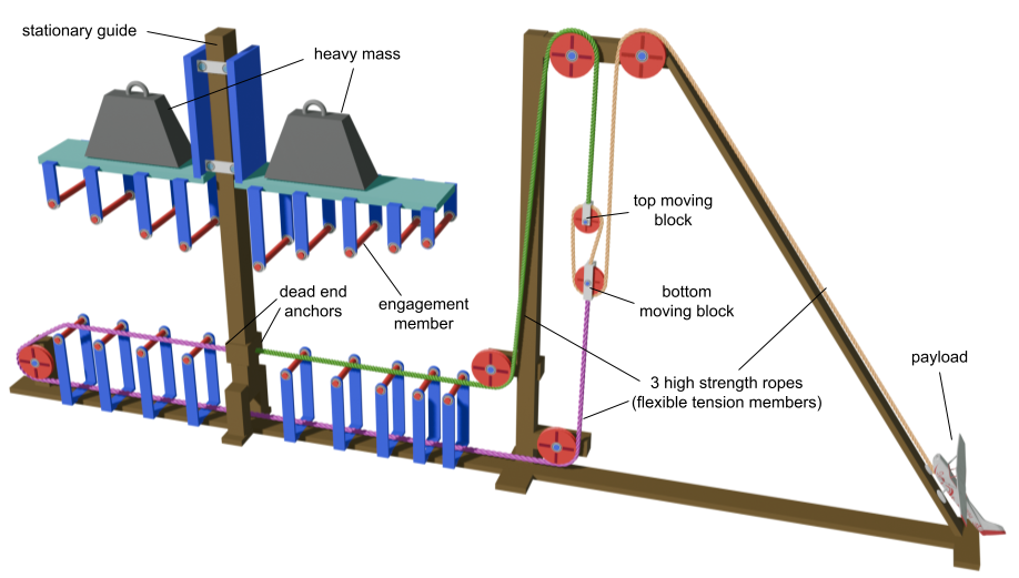
A tension member is reeved alternately over engagement members on a translating carriage and fixed supports, so carriage motion folds it into successive spans. One member of half-width R at depth D contributes
So the ratio rises through the stroke, asymptoting to 2 per member. For an array with offsets si and a fixed second stage k:
Closed form, no integration. Two independent freedoms per member — span width sets how fast a member contributes, offset sets when — and that pair is what lets an arbitrary rising profile be synthesised. Ceiling 2Nk.
Every member is concave; the target is convex
Every member bends the wrong way. The array reaches a convex target only as a chain of concave arcs staggered by their onsets — which is why offsets matter as much as widths, and where the force ripple comes from.
One member, and the staggered sum of several.
Specify the deceleration, not the force
State how hard the source is to be braked, and solve for the force that produces it. Ask for more than the array can reach and the machine gets worse, not merely shorter.
The worked convention is 10 m/s to 4 m/s in 0.100 s, leaving the source 16% of its entry energy over a 0.854 m braking distance, independent of mass ratio. Design force then scales as F ∝ √Mm , and the ideal exit velocity is v0 · √Mm to within a per cent — energy transfer is near total.
4 m/s is a knee, not a derived optimum. Above it the tension member stays loaded throughout; below it traction is lost. Braking to 3.0 m/s buys about 3.3% of exit velocity but carries peak force past the 1.3× bound in every case.
Design by fitting, not by search
Both the array ratio and the target are functions of source displacement, so finding the geometry is a curve fit over 2N parameters:
Plain squared residual — no weighting, no penalties, and no dynamic simulation inside the fit, which is what makes thousands of candidates affordable.
This matters because search does not work. Least squares beats 300,000 random samples by a factor of 7.7 on 150× fewer evaluations, and a structured grid over four intuitive parameters does worse than random sampling: the families a designer would naturally write down do not contain the optimum.
Compliance is required, not a refinement
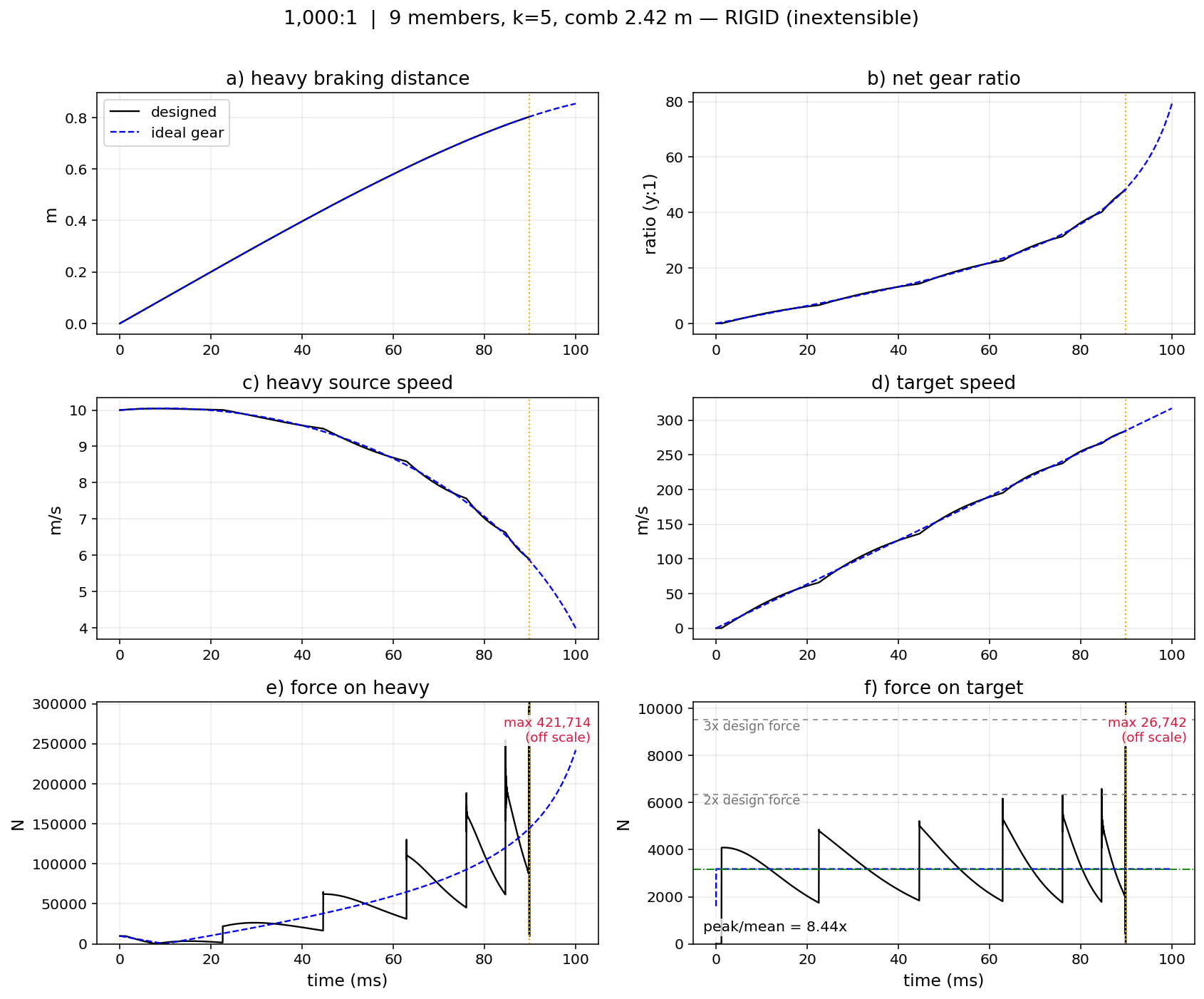
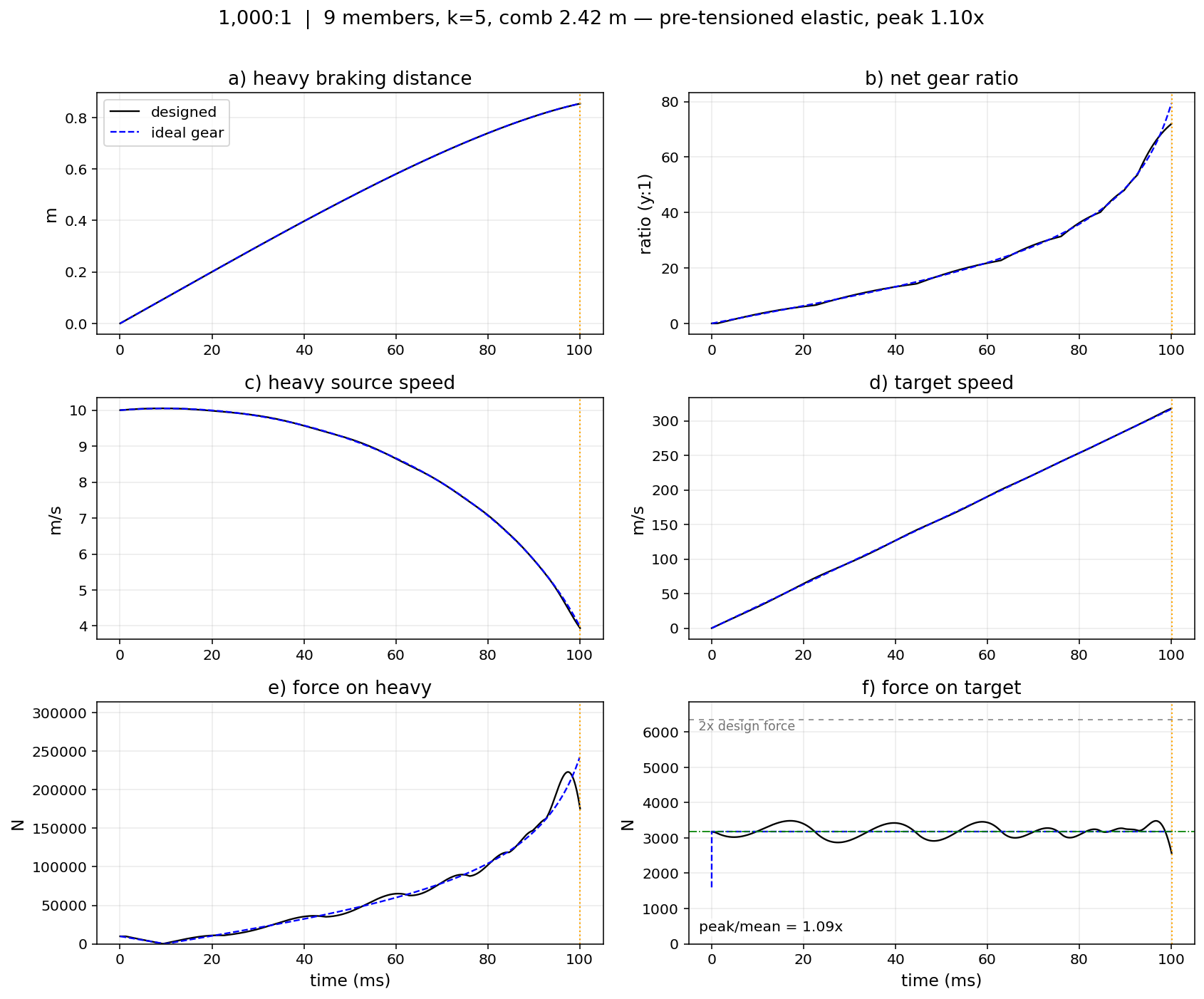
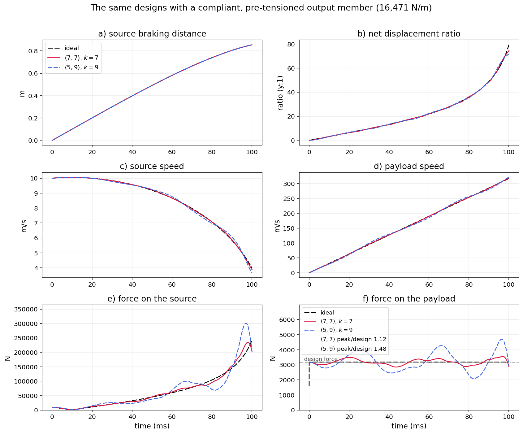
That sawtooth runs at about twice the mean in every canonical design. A compliant, pre-tensioned output member absorbs the transients:
| rigid | compliant | |
| 100:1 | 2.05× | 1.12× |
| 1,000:1 | 2.07× | 1.09× |
| 10,000:1 | 2.10× | 1.19× |
Pre-tension does the work, not compliance alone: started slack, the same apparatus rings at roughly 2.3×. And compliance cannot be engineered away — working strain is of order 1% whatever the fibre.
Severity follows the discreteness of engagement — not the fit residual, and not the mass ratio.
Where the energy goes
Measured against the work needed to raise the source again — through the braking distance as well as the height that set its entry speed — the transmission delivers 86.3% to the payload.
The source mass cancels: efficiency is fixed by entry speed, final speed and braking distance alone, and mass ratio cannot appear. The three simulated designs realise the analytic figure to within 0.4%.
Reality check
The largest omission is the rotational inertia of sheaves in the fast path, which acts exactly as added payload mass and costs a further 9 to 12% of exit velocity — more than any difference between the candidate geometries. Peak-to-mean force is a ratio and survives it; read the velocities as upper bounds.
The models are lossless and no apparatus has been built or measured. Every result here is theoretical or numerical, compared against steam and electromagnetic figures measured on fielded hardware.
The lateral load problem
Cards 09–12 build on doi.org/10.31224/8171 and a forthcoming paper on count-balanced arrays.
Everything above hangs off one side of the guide. The carriage reaction is about 23× the source weight — 228 kN at 1,000:1 — and every fold pushes along the guide, so what the bearings feel is its moment about the guide axis.
That moment cannot be trimmed away by placing the driving mass. Members engage in sequence along the array, so the centre of pressure sweeps outward from 0.25 m to 1.58 m through the stroke of the 2.42 m reference array, peaking at 360 kN m; any fixed offset leaves a moment that reverses sign mid-stroke.
Two bearings at spacing h react it as a couple, sliding at up to 10 m/s. With friction coefficient μ and reaction offset e, the guide loses a fraction
of the energy transferred, independent of mass ratio: at e/h = 0.5 a single array hands a fraction μ of its whole output to guide friction.
Two arrays, and why symmetry is not enough
Put an array on each side of a central guide. Each has its own tension member, dead-ended on the guide and driving its own counter-moving block at the stage, with the k output falls split between them. The net ratio is an exact weighted sum:
Two lines already pay: each carries njF rather than kF, and ⌊k/2⌋ elements leave the busiest rope path. Making the arrays mirror images then puts the reaction on both sides of the guide.
But a counter-moving stage is naturally odd, k = 2p + 1, so the falls cannot split evenly, and identical arrays pull unequally by |n1−n2|/k — 20% at k = 5, 14% at 7, 11% at 9. That is a property of the reeving, not a tolerance.
And identical arrays sum to kG, the single array’s ratio, so the payload sees the same force. Mirror symmetry changes where the load goes, never what the payload feels.
Balance by ratio, and by count
Each array pushes on the carriage with its falls × line tension × own ratio, so the guide balances when those products meet:
The array doing more work at the stage is the one made weaker. A fit can hold that through the middle of the stroke — but not at the end. Deep in the stroke every member saturates at 2, so Gj → 2Nj whatever the spans: the counts set the terminal balance, and equal counts drift straight back to the mirror residual. Hence the discrete condition:
Two ordering rules go with it: the array serving fewer falls engages first, and its excess members engage last. The geometry comes from one fit with a balance weight:
seeded from a single-array fit dealt alternately to the two sides, which already reproduces the net ratio. The counts carry the end of the stroke; the fit carries the middle.
What count balance delivers
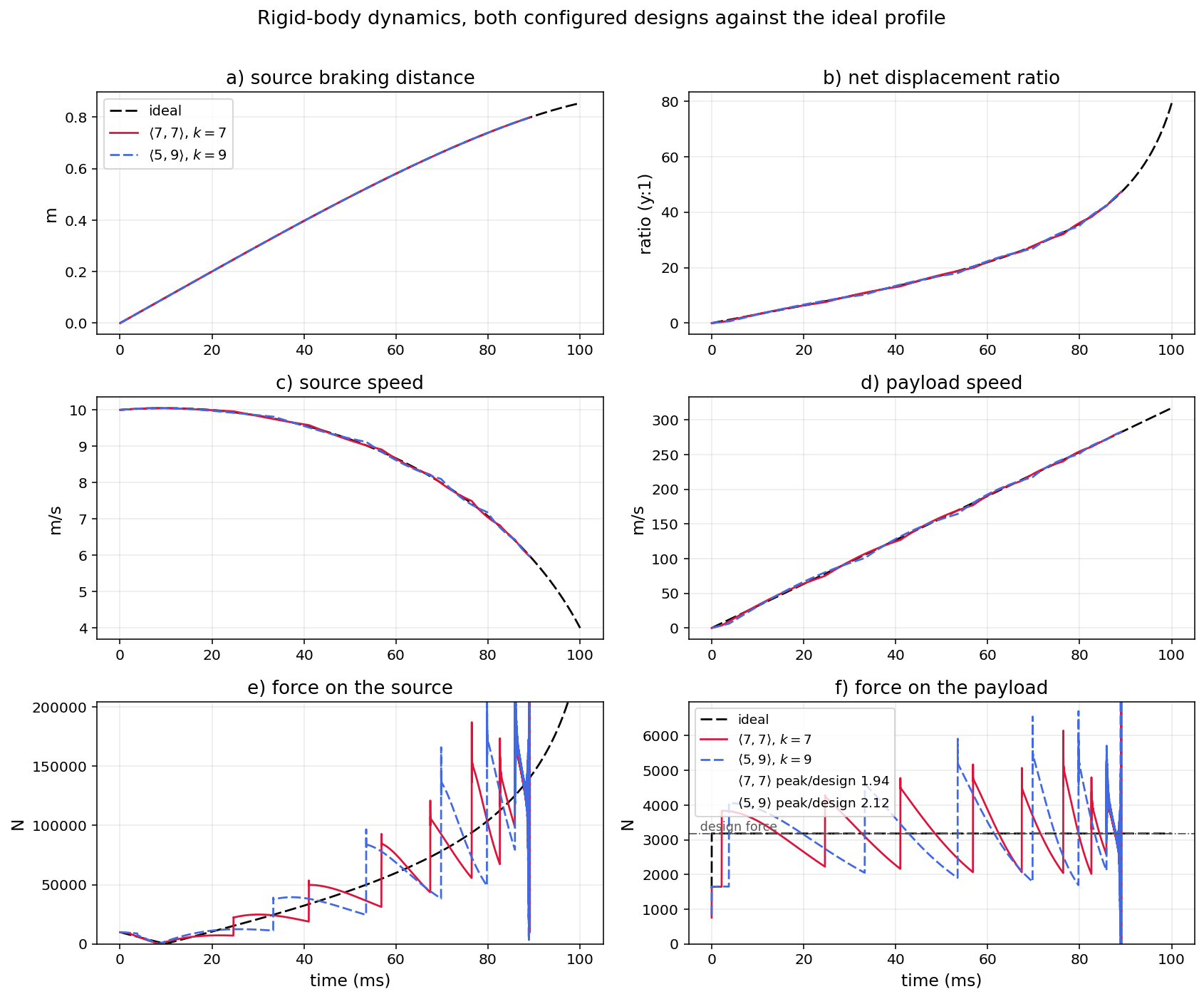
At 1,000:1 and k = 7, the same fourteen members arranged four ways:
| single | mirror | 7 : 7 | 8 : 6 | |
| peak/mean, compliant | 1.40× | 1.40× | 1.12× | 1.13× |
| peak/mean, rigid | 2.44× | 2.44× | 1.93× | 1.90× |
| reaction imbalance | one-sided | 14.3% | 8.1% | 2.3% |
| exit (m/s) | 321.0 | 321.0 | 318.7 | 318.8 |
Moving one 10 cm member from the trailing array to the leading one cuts the imbalance from 19.1 to 5.4 kN on a 235 kN reaction — 97.7% of the one-sided load cancelled — with the force profile untouched. On the moment the bearings actually react, it removes 95% of the single array’s 360 kN m.
At k = 9 the floor counts 5 : 4 buy minimalism instead: nine members in arrays under 1.2 m, 93% cancelled, 1.45× compliant. Past the counts, further balance is bought with width — 3.3 m arrays reach 0.5% at 1.29×.
Per-contact friction is the large term the lossless figures leave out: at 2% per contact every design keeps only 72–87% of its payload energy, the count-balanced pair 77% against a matched single array’s 72%.
Simulated; no dual-array machine has been built.
Simulated Dynamics — the 1,000:1 design
The Two Machines, Running
Both loop continuously. Geometry is illustrative and not to scale.
Set your own specification and let the solver search for a comb.
Peak force against array width — every candidate
Score = ((51 - N) / 50) × sqrt(exit_rigid × exit_compliant) / sqrt(0.5 × (peak2mean_rigid² + peak2mean_compliant²))
Mechanism
comb 1:1 · stage and payload rescaled, as labelledForce trace, ratio profile and the full numbers for this run.
Force on payload
Net ratio vs carriage displacement
Peak / mean force, launch systems compared
Run summary
System Geometry
Deceleration & Stroke
Velocity & Performance
What is computed here, and how far to trust it
The geometry is closed form and exact. The dynamics are integrated in the browser by a direct transliteration of the project's Python simulators, including the one-step gear lag, the trapezoidal update and the two-step averaged reaction.
The compliant integrator is verified against the three exported reference runs and reproduces them to the digit: exit velocity within 0.004 m/s, elapsed time within 0.001 ms, peak force within 0.02 N. The target solver returns F = 998.98 / 3169.63 / 10033.82 N against the published 999.0 / 3169.6 / 10033.8.
Peak-to-mean is reported over the first 99.5% of the force trace, the paper's convention: the release is specified to operate before the terminal traction-loss pulse, so that pulse is not experienced by the payload and including it would misstate the load.
The rigid trace is indicative only. Its termination parameters are not recorded in the reference data, and the run is chaotic in them. This matches the paper's own note that the terminal pulse is the one part of the trace that is not timestep-converged, and that establishing its magnitude would require sub-stepping to the contact transition. Use it to see that an inextensible member diverges, not to read how far.
The geometries shipped on this page predate the paper's joint selection of N and k. They are the earlier hand-selected designs, and their rigid peak-to-mean figures are the superseded 20×/6×/3× family rather than the 2.05×/2.07×/2.10× of the canonical designs. Where this page and the paper disagree, the paper is correct.
Why the solver ranks by simulation, not by fit
The fitting objective matches G, but payload force tracks its slope:
at = G′ vh2 + G ah
So residual predicts force badly. Measured here at 100:1: a fit with rms 0.43 — better than the reference design's 0.48 — produces a peak of 1.50× against the reference 1.24×. Every candidate is therefore simulated and ranked on its actual peak force.
That measurement was made under a target the array could not reach, which is the regime in which the landscape goes multi-modal and the residual stops predicting anything useful. Under a target set by the deceleration rule the landscape is effectively unimodal and restarts agree — within 2.4%, 0.7% and 0.1% on compliant peak-to-mean at 100:1, 1,000:1 and 10,000:1. The return from tuning the objective measures how badly the target is specified; it is a diagnostic, not a design tool. Simulating every candidate remains the safe ranking, but on a well-posed target it mostly breaks ties.
Where restarts do disagree, that spread is shown rather than hidden: it is a property of the problem, not of the solver.
Compliance is a requirement, not a refinement
With an inextensible member the payload outruns the rope tip, the member goes slack, and re-contact arrives as an impulse; successive impulses grow. Severity is governed by the discreteness of engagement — the arc length between successive members relative to the stroke — not by fitting fidelity.
Mass ratio does not order severity. Earlier work, including the reference geometries this page ships, reported severity ordered inversely to mass ratio by a factor of seven. That ordering was an artefact of hand-chosen configurations. Once N and k are selected jointly, the three cases fall within a factor of 1.02 (2.05×, 2.07×, 2.10× rigid) and the sign reverses — the lowest mass ratio is the best behaved rigidly.
Pre-tensioning to the working tension is what matters, not the stiffness value: started slack, the payload mode on that compliance gives roughly 2.3× with the member unloaded for some 11% of the stroke; pre-tensioned, the same apparatus is near 1.03× with no unloaded interval. The result is insensitive to stiffness over the plausible range, and to damping.
Known limits
- Sheave rotational inertia is absent from every model here — the largest single omission, and first-order rather than a correction. Applied post hoc it costs 9 to 12% of exit velocity (neff ≈ 2 to 3 acting as added payload mass). Peak-to-mean force is a ratio and survives it.
- The model is lossless, so energy figures are upper bounds. Friction, member mass and drag are also absent.
- No apparatus has been built or measured. Every figure here is theoretical or numerical, and the steam and electromagnetic figures it is compared against are measured on fielded hardware.
- Above roughly 1000 m/s the rope, not the geometry, becomes the binding constraint: v/c = 0.53 against a UHMWPE critical speed near 1900 m/s, and 0.92 at a safety factor of 3 — past the 0.577c power optimum.
- Minimum practical span is taken as 10 cm. Unconstrained fitting produces 2 cm spans whose slope jumps 2/R are of order 200, and those engage violently.
Algorithmic description of the rigid (inextensible-rope) RopeComb simulation. The carriage motion drives the payload through a rigid unilateral constraint: when the rope is taut, carriage deceleration directly accelerates the payload; if the rope goes slack, the payload enters free flight.
─────────────────────────────────────────────────────────────────────────────
 Algorithm: simulateRigid(M, m, h₀, G(d), dt)
─────────────────────────────────────────────────────────────────────────────
  Inputs
    M       ── source mass  (kg)
    m       ── payload mass (kg)
    h₀      ── source drop height (m); v₀ = √(2·g·h₀)
    G(d)    ── gear-ratio function of source displacement d (m)
    dt      ── time step (s);              default 2×10⁻⁵ s

  Outputs
    time-series of:  t, gear, v_source, v_payload, d_source,
                     d_payload, rope_end, F_source, F_payload, slack

─────────────────────────────────────────────────────────────────────────────

INITIALISE
  v_s    ← √(2·g·h₀)        ── source speed  (m/s)
  v_p    ← 0                 ── payload speed (m/s)
  d_s    ← 0                 ── source displacement (m)
  d_p    ── 0                 ── payload displacement (m)
  G_prev ← 0                 ── gear ratio at previous step
  G_avg  ← 0                 ── average gear over current step
  F_react_prev ← 0          ── reaction force at previous step (N)
  rope_end     ← 0          ── initial rope-end position (m)
  a_p_prev     ← 0          ── payload acceleration at previous step
  a_p    ← 0                 ── payload acceleration (m/s²)
  t      ← 0

LOOP  while  t < t_max  and  a_p < a_max
  t ← t + dt

  ── 1. Update source (heavy) body ─────────────────────────────────────────
  F_net_s    ← M·g  −  G_avg·F_react_prev   ── uses previous-step reaction
  a_s        ← F_net_s / M
  v_s_new    ← v_s + a_s·dt
  d_s_step   ← dt·(v_s_new + v_s) / 2       ── trapezoidal displacement
  d_s        ← d_s + d_s_step
  v_s        ← v_s_new

  ── 2. Update gear ratio ──────────────────────────────────────────────────
  G_new  ← G(d_s)                           ── evaluate comb geometry
  G_avg  ← (G_prev + G_new) / 2
  G_prev ← G_new

  ── 3. Advance rope end (kinematic) ──────────────────────────────────────
  rope_end ← rope_end + d_s_step · G_avg

  ── 4. Update payload body (unilateral rigid constraint) ──────────────────
  free_flight ← (v_p − 0.5·g·dt) · dt       ── free-flight displacement
  taut        ← rope_end − d_p              ── rope-limited displacement

  if free_flight > taut then
    d_p_step ← free_flight                  ── slack: payload is in free flight
    slack    ← true
  else
    d_p_step ← taut                         ── taut: payload constrained by rope
    slack    ← false
  end if

  d_p      ← d_p + d_p_step
  v_p_new  ← 2·(d_p_step / dt) − v_p
  a_p_new  ← (v_p_new − v_p) / dt
  v_p      ← v_p_new
  a_p      ← a_p_new

  ── 5. Compute reaction force ────────────────────────────────────────────
  a1 ← (g + a_p_prev) if a_p_prev > 0 else 0
  a2 ← (g + a_p_new)  if a_p_new > 0 else 0
  F_react_prev ← m · (a1 + a2) / 2

  a_p_prev     ← a_p_new

  ── 6. Record history ─────────────────────────────────────────────────────
  RECORD(t, G_new, v_s, v_p, d_s, d_p, rope_end,
         |F_net_s|, F_react_prev, slack)

END LOOP

RETURN history, peak_force, mean_force, exit_speed, elapsed_time─────────────────────────────────────────────────────────────────────────────
Algorithm: G(d) ─ instantaneous gear ratio of the comb at displacement d
─────────────────────────────────────────────────────────────────────────────
Inputs
R[1..N] ── half-widths of the N sheaves / buckets (m)
s[1..N] ── axial offsets of the N pins (m)
k ── number of rope wraps (stage count)
d ── current source displacement (m)
Output: total gear ratio G (dimensionless)
─────────────────────────────────────────────────────────────────────────────
FUNCTION G(d):
total ← 0
for i ← 1 to N do
D ← d − s[i] depth into sheave i
if D > 0 then
total ← total + 2·D / √(R[i]² + D²)
end for
return k · totalThe full Python reference implementation for the RopeComb simulation, fitting solver, and canonical cases has been packaged and published as an open-source library.
Python Reference Implementation
View the full repository, solvers, and simulation code on GitHub.